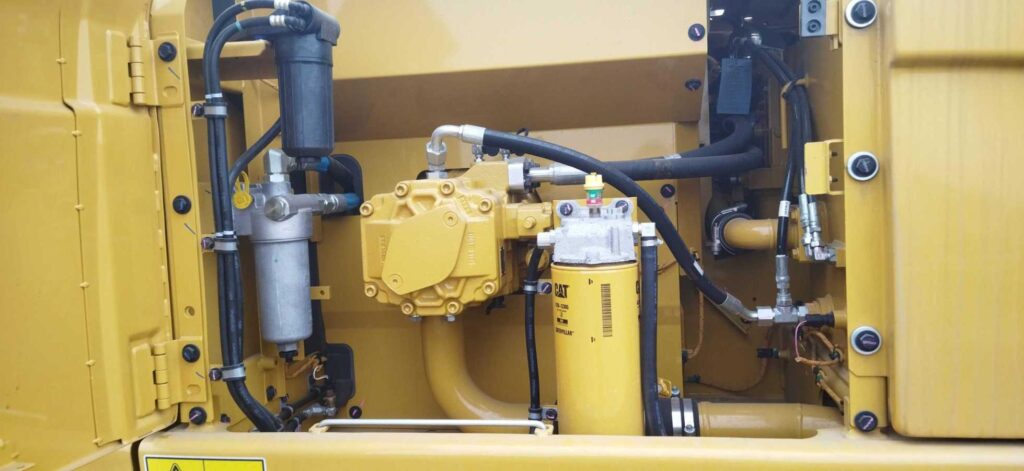
Main Hydraulic Pump
320, 320GC, 323, 325, FM538, 538……
Prefix: NGY, BR6, YBP, ZBN, BR9, DWE, DWF, HDT, KTY, RAZ, YBL, DYT, NMC, XAR, FJM, LTN, NDL, WME, GSR, GKW, DYG, FAY, GWP, HFF, JFH, RWF, SNN, YHW, ZRJ (Hydraulic Pump)
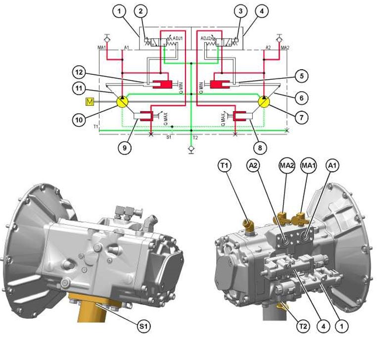
) Regulator (pump 1)
(2) Control solenoid (pump 1)
(3) Control solenoid (pump 2)
(4) Regulator (pump 2)
(5) Counter piston (pump 2)
(6) Swashplate (pump 2)
(7) Pump 2
(8) Stroking piston (pump 2)
(9) Stroking piston (pump 1)
(10) Pump 1
(11) Swashplate (pump 1)
(12) Counter piston (pump 1)
(A1) Outlet port (pump 1)
(A2) Outlet port (pump 2)
(MA1) Pressure tap (pump 1 pressure)
(MA2) Pressure tap (pump 2 pressure)
(S1) Inlet port (supply oil from the hydraulic tank)
(T1) Case drain port
(T2) Pressure tap (case drain oil)
Supply oil from the hydraulic tank enters inlet port (S1). The single inlet port is common to main hydraulic pumps (10) and (7). Pump 1 (10) delivers oil through outlet port (A1). Pump 2 (7) delivers oil through outlet port (A2).
Case drain oil from the hydraulic pump housing flows from port (T1) to the case drain filter.
The main hydraulic pumps consist of pump 1 and pump 2. The hydraulic pumps are connected in series by center manifold. Both pumps are variable displacement piston pumps. The displacement is controlled by pump regulators (1) and (4). The pump 1 and the pump 2 are identical in construction and operation.
Both pump 1 and pump 2 have an electronically controlled regulator as part of the pump control system. The flow control of the pumps is performed by the operation of the regulators. The control system is identical for both pumps.
Hydraulic Pump control solenoids (2) and (3) for the pump regulators are located on the side of the main pump. The hydraulic pump control solenoids are controlled by the machine ECM. The hydraulic pump control solenoid controls the pump pressure signal to stroking piston (9). The stroking piston and counter piston then controls the angle of swashplate (11).
Operation
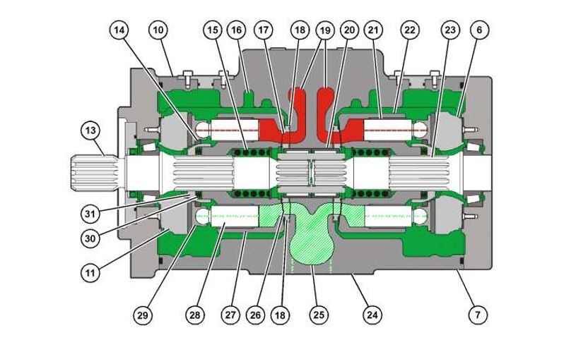
| Main Hydraulic pumps (sectional view) (typical example) (6) Swashplate (pump 2) (7) Pump 2 (10) Pump 1 (11) Swashplate (pump 1) (13) Shaft (14) Plate (15) Spring (16) Case drain oil (17) Passage (18) Port plate (19) Passage (20) Coupling (21) Piston (22) Barrel (23) Shaft (24) Center manifold (25) Passage (26) Passage (27) Barrel (28) Piston (29) Slipper (30) Spring (31) Guide |
The engine crankshaft drives the hydraulic pumps. The engine is connected to shaft (13) through the coupling in the flywheel housing. Shaft (13) is connected to shaft (23) by coupling (20). Barrel (27) is splined to shaft (13). Barrel (22) is splined to shaft (23). Barrel (27) and barrel (22) contain sets of pistons. Pistons (28) and (21) rotate with the barrels. Pistons (28) rotate about swashplate (11), and pistons (21) rotate about swashplate (6). As the angle of swashplate (11) and swashplate (6) increases, the pistons will extend and retract within the barrels. The extending and retracting of the pistons will cause oil to flow from inlet port (S1) to outlet ports (A1) and (A2). The pump shafts, barrels, and pistons all rotate together within the hydraulic pump housing.
Each piston (28) is attached to a slipper (29). All of the slippers are contained in plate (14). Guide (31) contacts plate (14) and forces slippers (29) against the swashplate with springs (30). Pistons (28) rotate around swashplate (11) with slippers (29).
Note: The operation of pump 1 is described below. Pump 2 operates in the same manner as pump 1.
When shaft (13) rotates, barrel (27) and pistons (28) rotate. As barrel (27) rotates, oil is drawn from inlet port (S1) to inlet passage (25). The oil in passage (25) flows to passage (26) at port plate (18). The oil fills in the voids of barrel (27).
The angle of swashplate (11) causes pistons (28) to be retracted from barrel (27) at passage (26). When pistons (28) align with passage (17), the swashplate causes pistons (28) to be extended into barrel (27). As barrel (27) rotates, passage (26) is closed off from the voids in barrel (27). Swashplate (11) forces pistons (28) into barrel (27). Pistons (28) pressurize the oil inside barrel (27). As barrel (27) continues to rotate, the oil pressure in barrel (27) is able to flow into passage (17) of port plate (18). Oil flows from passage (17) to outlet port (A1). Oil flow is provided to the main hydraulic system.
The angle of swashplate (11) determines the stroke length of pistons (28). The angle of swashplate (11) is controlled by the regulator.
Operation of regulators
The regulators for pump 1 and pump 2 are identical in construction and operation. The pump regulators are located on the sides of the main pump housing. The following description is given for the pump 1 regulator.
The pump regulators are controlled by the electronic control system. The machine ECM continually monitors various inputs. The machine ECM sends a pulse width modulated (PWM) driver to the pump control solenoid on the pump regulators. Pump control solenoid controls the output flow of the pump by changing the hydraulic signal pressure that flows to the counter piston.
The machine ECM controls the PWM driver sent to the pump control solenoid and determines the required pump flow based off the following inputs.
Desired engine speed – Determined by the engine speed dial.
Actual engine speed – Determined by the engine speed pickup.
Hydraulic torque output – The hydraulic torque output varies depending on the engine speed dial setting.
Pump 1 displacement – Determined by pump 1 control solenoid current.
Pump 2 displacement – Determined by pump 2 control solenoid current.
Flow requested – Determined by the left-hand joystick position, right-hand joystick position, or the travel pilot pressure sensors.
Pump 1 delivery pressure – The pump 1 delivery pressure is measured by the pump 1 pressure sensor on the main control valve.
Pump 2 delivery pressure – The pump 2 delivery pressure is measured by the pump 2 pressure sensor on the main control valve.
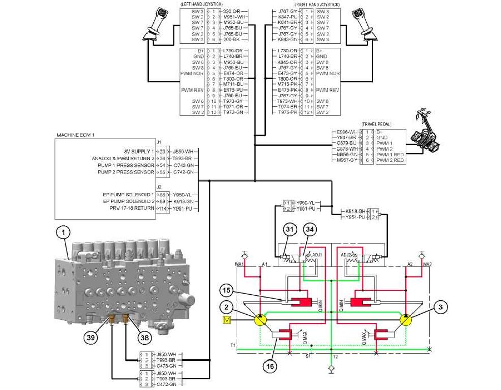
Partial schematic
(1) Main control valve
(2) Pump 1
(3) Pump 2
(15) Counter piston (pump 1)
(16) Stroking piston (pump 1)
(31) Pump 1 control solenoid
(34) Pump displacement spool
(38) Pump 1 pressure sensor
(39) Pump 2 pressure sensor
The machine ECM sends a PWM driver to pump control solenoid (31) to control the angle of the pump swashplate. When current decreases the pump destrokes. Pump control solenoid (31) directs oil to the stroking piston (16) to destroke the pump.
When current increases the pump upstrokes. Pump control solenoid (31) directs pump oil to the end of counter piston (15) in order to upstroke the pump.
The P-Q characteristic curve is determined by the machine ECM. The output characteristic of each pump depends on the following inputs.
- Desired engine speed
- Actual engine speed
- Hydraulic torque output
- Pump 1 displacement
- Pump 2 displacement
- Flow requested
- Pump 1 delivery pressure
- Pump 2 delivery pressure
The flow rate of each pump is represented on P-Q characteristic curve (B) from pressure/flow point (A). Each point on the P-Q characteristic curve represents the flow rate and pressure when pump output horsepower is maintained at a constant rate.
Pump Regulator
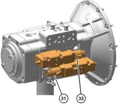
Pump regulators
(31) Pump 1 control solenoid
(32) Pump 2 control solenoid
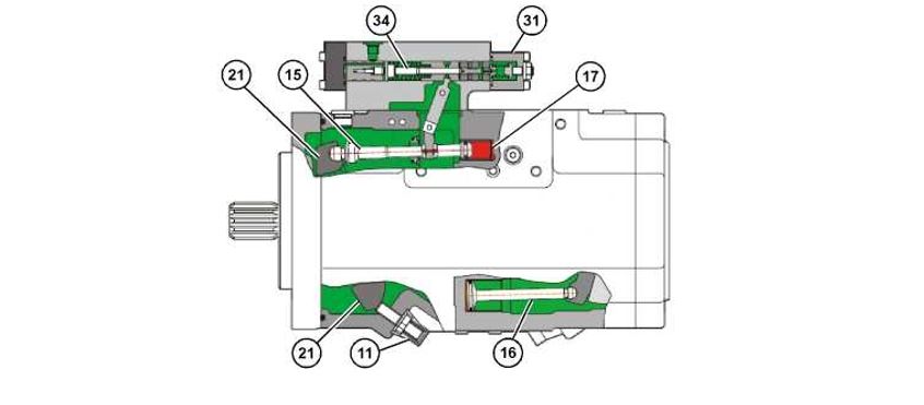
| Pump 1 regulator (11) Maximum angle stop screw (15) Counter piston (16) Stroking piston (17) Minimum angle end of counter piston (21) Swashplate (31) Pump control solenoid (34) Pump displacement spool |
Illustration 6 shows the separate control sections of the pump control group. The control sections work together to regulate pump flow by changing the angle of the pump swashplate, according to demand and hydraulic horsepower requirements.
Pump delivery pressure is directed to the end of the counter piston (15) to upstroke the pump toward the maximum angle. The pump swashplate is connected to counter piston (15).
Pump pressure acting on the end of counter piston (15) works with pump displacement spool (34) to destroke the swashplate when all hydraulic controls are in the NEUTRAL position or during an implement or travel function when hydraulic demand decreases. The counter piston (15) works with pump displacement spool (34) to upstroke the swashplate when the hydraulic demand increases. The stroking piston (16) works with pump displacement spool (34) to destroke the swashplate when the hydraulic demand decreases.
Pump displacement spool (34) is controlled by pump control solenoid (31) and spring (40).
Pump oil is supplied to passage (35) and flows to the end of counter piston (15). Pump oil also flows through passage (41) to pump displacement spool (34). The oil pressure in passage (35) can now be regulated by pump displacement spool (34) to supply a hydraulic signal pressure.
When pump control solenoid (31) receives a PWM driver from the machine ECM, pump displacement spool (34) shifts. Oil pressure can now flow through passage (42) to the stroking piston (16). This action causes the pump to upstroke.
Regulator Operation (Standby – Full Destroke)
the pump regulator and swashplate in the destroke position. When all hydraulic control valves are in NEUTRAL position, the pump swashplate is held in the standby condition.
The machine ECM sends a PWM driver decrease the current at pump control solenoid. Pump control solenoid causes pump displacement spool to shift by the force of spring . Oil then flows through passage to the stroking piston . Swashplate moves to the destroke position causing the pump to destroke.
Regulator Operation (Constant Flow)
Pump oil enters passage and acts on the end of counter piston . Part of the pump oil flows through passage and to pump displacement spool .
The machine ECM sends a PWM driver to increase the current at pump control solenoid . Pump control solenoid causes pump displacement spool to shift against the force of spring. Metered signal oil then flows through passage to the stroking piston. The oil to and from the stroking piston is metered by pump displacement spool. The angle of swashplate remains constant until the machine ECM changes the electrical signal to pump control solenoid.
Regulator Operation (Flow Increase – Full Upstroke)
Pump oil enters passage and acts on the end of counter piston.
The machine ECM sends a PWM driver to increase the current at pump control solenoid to upstroke the pump. Pump control solenoid causes pump displacement spool to shift against the force of spring . The greater the commanded signal supplied to pump control solenoid the greater the pump displacement will be. The pump will upstroke until stroking piston contacts maximum angle stop screw.
Related posted:
https://equipmentguider.com/how-to-maintain-your-equipment-a-complete-guide/
Follow us on Facebook page.
Frequently ask questions
What is the main hydraulic pump?
The main hydraulic pump is the heart of a hydraulic system. It converts mechanical energy (usually from an engine or motor) into hydraulic energy by creating a flow of pressurized fluid. This fluid then powers various hydraulic components like cylinders, motors, and valves, enabling machines to lift, push, or move heavy loads efficiently.
What are the three main types of hydraulic pumps?
There are three primary types of hydraulic pumps used in different applications:
Gear Pumps – Simple, cost-effective, and reliable, commonly used in low-to-medium pressure systems.
Piston Pumps – High-efficiency and capable of handling higher pressures, often found in industrial and heavy-duty machinery.
Vane Pumps – Known for smooth operation and moderate pressure handling, frequently used in mobile and industrial applications.
What is the most common hydraulic pump?
Gear pumps are the most commonly used hydraulic pumps due to their durability, affordability, and ease of maintenance. They are widely used in industrial machines, agricultural equipment, and construction vehicles.
What is the use of a hydraulic pump?
A hydraulic pump is used to generate and direct fluid power in hydraulic systems. It supplies pressurized fluid to operate heavy machinery, construction equipment, forklifts, aircraft systems, and even power steering in vehicles. Essentially, it makes movement and force transmission possible in hydraulic-powered systems.