Description:
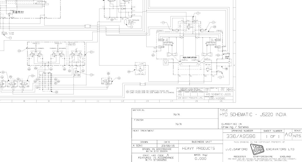
A hydraulic circuit diagram is a schematic representation of how hydraulic components are connected and work together within a hydraulic system. It shows the flow of hydraulic fluid, the control valves, pumps, actuators (like cylinders or motors), and other components. These diagrams are used to design and troubleshoot hydraulic systems.
Here’s a simple breakdown of the key components you might see in a basic hydraulic circuit diagram:
- Hydraulic Pump: Provides the flow of hydraulic fluid under pressure to the system.
- Reservoir: Stores the hydraulic fluid.
- Control Valves: Directs the flow of fluid to the appropriate actuator, such as directional control valves.
- Actuators (Cylinders/Motors): Convert hydraulic energy into mechanical work.
- Pressure Relief Valve: Protects the system from overpressure by diverting excess fluid back to the reservoir.
- Flow Control Valves: Regulates the speed of actuators by controlling the flow of hydraulic fluid.
- Filter: Cleans the fluid before it reaches the components to prevent damage.